Overview
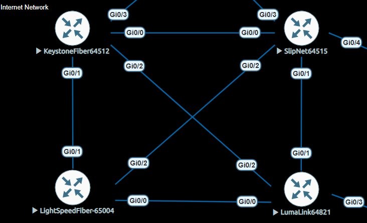
This lab simulates a realistic internet exchange core built in EVE-NG using Cisco IOSv routers and a pfSense firewall running FRRouting. Each of the 4 ISP routers represents an autonomous system. Point-to-point OSPF links form the physical mesh, giving every router redundant paths to every other router's loopback. eBGP sessions then form over those loopbacks — the same way real ISPs peer with each other.
A fifth router, City Core 1 (ASN 65001) running FRRouting on pfSense, acts as the upstream transit provider — originating a default route into the ISP mesh, peering with an upstream provider, in this instance its my main firewall which then NATs you out to the real internet if needed, and applying outbound BGP policy to prevent routing loops.
Node Inventory
| Hostname | ASN | Loopback0 | Platform | Role |
|---|---|---|---|---|
| KEYSTONE-FIBER | 64512 | 140.140.140.140 | Cisco IOSv | ISP Core |
| SLIPNET | 64515 | 141.141.141.141 | Cisco IOSv | ISP Core |
| LIGHTSPEED-FIBER | 65004 | 142.142.142.142 | Cisco IOSv | ISP Core |
| LUMA-LINK | 64821 | 143.143.143.143 | Cisco IOSv | ISP Core |
| CITY-CORE-1 | 65001 | 144.144.144.144 | FRRouting / pfSense | Transit / Upstream |
OSPF Underlay
OSPF runs across all 6 point-to-point /31 links between the 4 ISP routers, plus the two uplinks to City Core. Its only function is to distribute loopback /32 addresses so eBGP sessions can form between non-directly-connected peers. No customer or external prefixes enter OSPF.
- All ptp interfaces set to
ip ospf network point-to-point— no DR/BDR elections on /31s - Interface-level OSPF assignment used instead of network statements
- Only loopback /32s advertised — ptp links included automatically via interface assignment
- MD5 authentication on City Core uplinks
- Single Area 0 throughout
interface GigabitEthernet0/0
 ip ospf network point-to-point
 ip ospf 1 area 0
!
router ospf 1
 router-id 140.140.140.140
 network 140.140.140.140 0.0.0.0 area 0
BGP Design
All 4 ISP routers maintain eBGP sessions with each other — a full mesh of 6 sessions. Sessions form over loopback addresses, decoupling BGP stability from any single physical link failure. Two directives are required on every neighbor statement when peering over loopbacks:
ebgp-multihop 2— permits the BGP TCP session to traverse one intermediate hopupdate-source Loopback0— sources the session from the loopback, not the outgoing interface
router bgp 64512
 neighbor 141.141.141.141 remote-as 64515
 neighbor 141.141.141.141 ebgp-multihop 2
 neighbor 141.141.141.141 update-source Loopback0
 neighbor 142.142.142.142 remote-as 65004
 neighbor 142.142.142.142 ebgp-multihop 2
 neighbor 142.142.142.142 update-source Loopback0
 neighbor 143.143.143.143 remote-as 64821
 neighbor 143.143.143.143 ebgp-multihop 2
 neighbor 143.143.143.143 update-source Loopback0
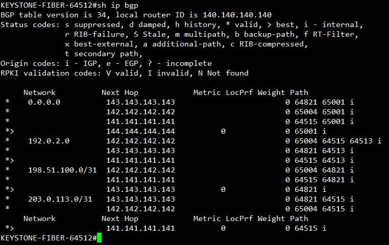
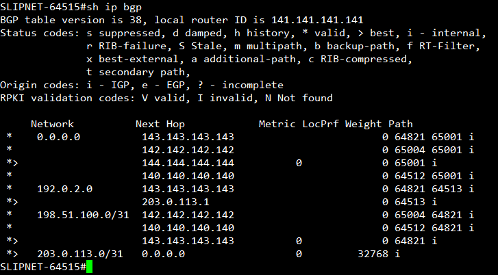
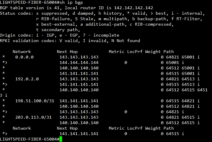
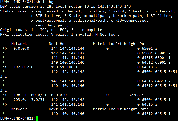
BGP Tables
All 4 ISP routers show a consistent full table — default route from City Core, customer prefixes propagated across the mesh, and correct AS path attribution to each origin AS.
City Core BGP Policy
City Core 1 peers with all 4 ISPs via eBGP over OSPF-learned loopbacks. It originates a default route to all ISP neighbors and has a default route from my main firewall getting traffic out to the internet.
Loop Prevention
192.0.2.0/24 originates from a customer with two routers connected to SLIPNET and LUMALINK. Without outbound filtering, City Core would readvertise this prefix back into the ISP mesh — ISPs would learn it from City Core rather than the originator, creating a loop.The BLOCK_NEWARK_NETS route-map applied outbound to all 4 ISP neighbors blocks it. In this instance the customer has its own IP space that it will like to advertise out to the "internet" so eBGP peers are formed with the customer's MikroTiks to the SLIPNET and LUMALINK routers.
permit 0.0.0.0/0 which only matches the exact default route — not all prefixes. The implicit deny at the end of the route-map was silently dropping everything else outbound to the ISPs. Fixed by adding le 32 to match all prefixes (/0–/32) and adding a trailing permit 10 clause with no match condition to pass everything not explicitly denied.
ip prefix-list BLOCK-NWK-WAN seq 5 deny 192.0.2.0/24
ip prefix-list BLOCK-NWK-WAN seq 10 permit 0.0.0.0/0 le 32
!
route-map BLOCK_NEWARK_NETS deny 5
 match ip address prefix-list BLOCK-NWK-WAN
route-map BLOCK_NEWARK_NETS permit 10
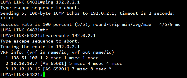
End-to-End Reachability
LUMA-LINK successfully reaches the Newark customer prefix (192.0.2.0/24). All ISP routers in this topology maintain knowledge of the prefix through BGP, allowing traffic from any connected network to be forwarded toward Newark. For example, if a customer connected to LIGHTSPEED-FIBER sends traffic destined for 192.0.2.0/24, the router determines the correct outbound interface based on its BGP table. This behavior mirrors how the internet operates at scale, where distributed routing information enables global reachability.
When testing reachability to 192.0.2.1, the destination represents an IP address on a WAN distribution switch within the Newark network. Newark operates a Layer 3 internal architecture, meaning traffic destined for this address is routed through Newark’s internal network until it reaches the destination. This confirms that internal routing and external BGP path selection are functioning correctly.
The Newark network was designed with redundancy as a primary objective. While EVE-NG does not support advanced technologies such as switch stacking or MC-LAG, high availability was achieved through the use of dynamic routing protocols and fast failure detection. Bidirectional Forwarding Detection (BFD) was implemented alongside OSPF and BGP to significantly reduce convergence time. In the event of a Layer 3 device failure, routing adjacencies are lost quickly, allowing traffic to reconverge with minimal disruption.
The Newark customer topology consists of two MikroTik edge routers, each independently peering with upstream ISP routers via eBGP and advertising the 192.0.2.0/24 prefix into the network. These routers connect to two core Layer 3 Cisco switches, forming an internal iBGP environment for route exchange. OSPF is used downstream from the core layer to provide redundant connectivity to remote sites such as City Hall, the Police Department, and other critical infrastructure. This layered design ensures resiliency and scalability within the constraints of the lab environment. Additional documentation on the Newark network will be provided in a future update.
Conclusion
This lab successfully demonstrates a multi-AS internet simulation using BGP over an OSPF underlay, replicating real-world ISP peering and routing behavior. Each autonomous system independently advertises and learns routes, allowing traffic to traverse the network based on BGP path selection and routing policies.
Through validation testing, both successful and failed connectivity scenarios were observed and analyzed. These tests highlight key networking principles such as the importance of return paths, the role of advertised prefixes in BGP, and the interaction between external and internal routing protocols.
Additionally, the Newark network was designed with redundancy and high availability in mind, leveraging dynamic routing protocols and BFD to achieve fast convergence during failures. While certain technologies such as MC-LAG and switch stacking were not available in the lab environment, the design effectively simulates enterprise grade resiliency using available tools.
This project reflects a strong understanding of routing architecture, protocol interaction, and network design principles, forming a solid foundation for more advanced topics such as traffic engineering, route filtering, and BGP security.
Skills Demonstrated
- Multi-AS BGP design and route propagation
- OSPF underlay for loopback-based peering
- eBGP multihop and loopback peering configuration
- Routing redundancy and failover design
- Network convergence optimization using BFD
- End-to-end path validation and troubleshooting
- Understanding of return path and asymmetric routing behavior